Sound Examples
A collection of Sound, MIDI, and I2S examples for Arduino
Setup
Introduction
Tone
Melody
MIDI
MIDI USB
MIDI Serial
MIDI to the VS1053 module
MIDI BLE
MIDI Controllers
I2S
VS1053 MP3 playback
Inventory
This project is maintained by tigoe
Setting Up To Build Projects
All of the projects in these examples will need a similar setup.
Install the Arduino IDE
First you’ll need the Arduino programming application (called an Integraded Development Environment, or IDE) Download the Arduino IDE for your personal computer and install it. AS of this writing, the current version is 1.8.8. You can use either the downloaded IDE or the web editor but the instructions here will all be for the downloaded version.
If you’re brand new to Arduino, you may want to read through a longer guide like Getting Started with Arduino, 3rd edtion by Massimo Banzi and Michael Shiloh.
Once you’ve downloaded the IDE, check out the Getting Started Guide for Arduino and the guide for the MKRZero or the guide for the MKR Wifi 1010.
Install the Board Definitions and Libraries
For both boards, you’ll need to open the Tools menu, then Boards Manager, then filter your search for MKR. You’ll see a package called Arduino SAMD Boards (32-bits ARM Cortex-M0+) by Arduino. Click Install. When it’s installed you can close the Boards Manager.
Next, Click on the Sketch Menu, choose Include Library… then Manage Libraries. filter your search for ArduinoSound and install it. Then filter your search for MIDIUSB and install it. You’ll use these libraries in many of these examples.
When you write your first Arduino program (called a sketch), the IDE will save it, and all your other sketches, in a folder called Arduino in your Documents folder, unless you specify otherwise.
That’s enough to get your IDE set up. Now let’s move on to the solderless breadboard.
Set Up the Breadboard
The solderless breadboard holds your microcontroller and other components, and lets you connect them together using jumper wires. The two long rows of holes down either side of the board are connected vertically. They’re called buses, and usually the red one is called the voltage bus or power bus, and the blue or black one is called the ground bus. You need connections to voltage and ground for every circuit you build, and the buses make it easy to set those up. The short rows of holes in the center of board are connected horizontally to each other with a break in the middle. These are where you connect components.
Figures 1 and 2 below show what’s underneath the holes,and how they are connected.
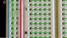
Figure 1. How the holes of a breadboard are connected
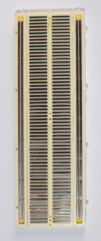
Figure 2. The back of the breadboard, showing the metal strips connecting the holes
The MKR Zero and MKR WiFi 1010 both have the same layout of input and output pins and power and ground pins, so you can use the same basic wiring for both. The USB connector is at the top of the board. The voltage and ground pins are on the right hand side. The analog input pins are on the left hand side towards the top, and the digital input and output pins are on the bottom left and along the right hand side. Figure 3 below shows the MKR pin layout, and the tables on either side of it list the pin functions, top to bottom on each side.
MKR Pin Layout
| Left side pins | Right side pins | |
|---|---|---|
| AREF A0/DAC0 A1 (INT) A2 (INT) A3 (PWM) A4 (PWM) A5 A6 D0 (INT) D1 (INT) D2 (PWM) D3 (PWM) D4 (PWM) (INT) D5 (PWM) (INT) |
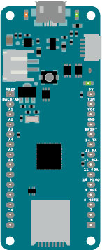 Figure 3. MKR pin layout |
5V Vin - voltage in, 5V max. Vcc - 3.3V GND - ground reset D14 and Serial1 TX D13 and Serial1 RX D12 and I2C SCL D11 and I2C SDA D10 and SPI SDI (PWM) D9 and SPI SCK D8 and SPI SDO (PWM) (INT) D7 (PWM) (INT) D6 and built-in LED (PWM) (INT) |
Note: Most pins have multiple functions. (PWM) indicates that a pin can be used with the analogWrite function. (INT) indicates that a pin can be used as an external interrupt.
This physical layout is sometimes referred to as a DIP, or Dual Inline Package. In a DIP package, physical pins are typically numbered from top left to bottom left, then from bottom right to top right. So physical pin 1 has the function Analog in 0, or A0; physical pin 14 has the function D5, or digital I/O 5; physical pin 15 has the function D6, or digital I/O 6; and pin 28 has the function 5V, or 5 volts supplied from the USB input.
The pins you’ll use all the time are the third from the top on the right (physical pin 26), Vcc, which outputs 3.3 volts when the board is connected to a USB power source or a battery, and the fourth from top on the right (physical pin 25), GND, which is the ground pin. Remember, voltage is always a relative measurement between two points. The Vcc pin’s voltage is measured relative to ground.
Breadboard Setup
Plug your MKR into your breadboard with the top pins in the top row of the board. Connect the GND pin on the right side (physical pin 24, numbering the pins in a U pattern as described above) the rightmost vertical column of holes on the breadboard on the right side. This will be called the ground bus. Similarly, the inner row on the right side will be called the voltage bus, and you should connect it to the row where Vcc pin of the Arduino (physical pin 25) is plugged in. Use two wires at the bottom of the board connect these two vertical rows to the corresponding vertical rows on the left side of the board. In this way, both the left and right sides of the board get a voltage bus row and a ground bus row.Figure 4 shows the board connected this way. The figure is rotated counter-clockwise so that the right hand side bus is on the top. Most of the circuit diagrams in these examples will be shown this way.
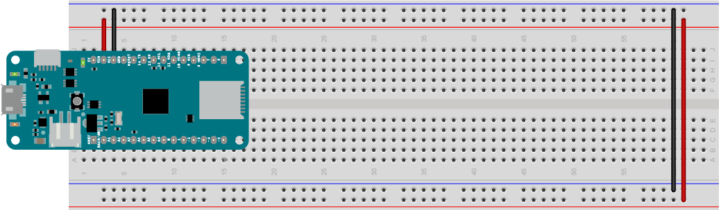
Figure 4. MKR Zero on a breadoard with Vcc and GND connected to the voltage and ground bus rows. The bus rows are also wired to their counterparts on the opposite side
Upload an Arduino Program
The first Arduino Arduino program, or sketch, that most people write is called Blink. It blinks an LED on the board. There’s a built-in LED on the MKR boards attached to pin 6. But since these are sound examples, let’s start with an example that makes noise. Attach one end of a 220-ohm resistor to the same row as pin 5 of the MKR board, and the other end to one of the other short rows of the breadboard. Then attach an 8-ohm speaker to that same row, as shown in Figure 5.
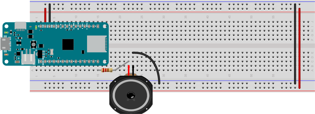
Figure 5. Speaker attached to pin 5 of a MKR Zero. The resistor limits the current to the speaker to protect it.
Now, type the following code into the Arduino IDE.Save this sketch with the name ToneSimple:
void setup() {
  // make the speaker pin an output:
  pinMode(5, OUTPUT);
}

void loop() {
  // turn the speaker on at 440Hz:
  tone(5, 440);
  delay(500);
  // turn the speaker off:
  noTone(5);
  delay(500);
}
Now plug your board into a USB port of your personal computer. Next, click on the Tools menu, then choose Board, then Arduino MKRZERO. Click the Tools menu again, choose Port, then look for a port with the subtitle (Arduino MKRZERO). On Windows, it will be called COM3 or a higher number. On MacOS, it may be called /cu/usbmodem1411 or another number. Finally, compile upload the sketch to your board by clicking the Sketch menu and choosing Upload. You can also do this by typing ctrl-U (command-U on MacOS), or clicking the Upload button on the editor window toolbar. Figure 6 shows the toolbar, with the upload button highlighted.
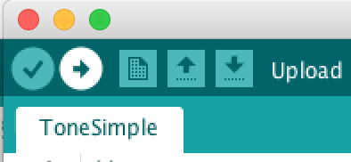
Figure 6. The Upload button is the second from left on the toolbar
Once you upload the sketch, your speaker should start playing a note at middle A (440 Hertz) every half second. Now you know everything is working properly. You should also see the following text in the error console at the bottom of the editor window:
Verify 10952 bytes of flash with checksum.
Verify successful
done in 0.010 seconds
CPU reset.
Programming Syntax: Parts of an Arduino Sketch
Now that you’ve got your sketch wotking, it’s worth reviewing some of the elements of it for future use.
The Arduino programming environment uses the C programming language and the grammatical style, or syntax, comes from C. Every line in a C program ends with a semicolon. Double slashes (//) indicate that the rest of the line should be ignored, so you can use them to make comments for yourself in your code. YOu can make multi-line comments in between /* and */ markers.
Every programming language needs places in memory to store information. These are called variables, and though you didn’t use any here, you’ll see them a lot in the future. C requires that you initialize every variable with a variable type, such as an integer (type int) or a floating-point decimal number (type float). Even nothing is a type, called void.
There are two functions in the sketch, called setup() and loop(). Functions are sets of instructions. Sometimes they return a value when they complete. The setup function runs once when the Arduino is reset. The loop runs continuously. When it finishes running, it starts again. It runs as long as the Arduino is powered. You’ll write other functions later, and you’ll use them by putting their names in your program.
Functions have a value type that they return. Both of these functions return nothing, so their type is void. Later you might see functions that return integer numbers. Their type would be int. Functions also have parameters. Parameters are what you fill in in the parentheses. If the function name is a verb, then the parameters are the direct objects, adjectives, and adverbs of a function. For example, tone() is a function (built-in functions are sometimes also called commands), and it has two parameters: the pin number that you want to write to, and the frequency that you want to give the pin. So tone(5, 440); sets pin 5 changing 440 times a second. The delay() function stops the program for an amount of time, and its parameter is the number of milliseconds that you want to stop for. So delay(500); stops program for 500/1000 of a second, or half a second.
Blocks of code that are all dependent on the same conditions are set off by braces like this {}. For example, all the code inside a function is dependent on you calling the function. So the syntax for a function needs a function type a name, parentheses for parameters, and braces to hold the code inside it, like so:
void loop() {

}
Here’s an overview of programming terms and environments that will familiarize you with the IDE and the terms you’ll encounter a bit more.
The collection of functions of any programming environment are called the Application Programming Interface (API). The Arduino API reference pages can be found online, and can also be accessed from the IDE’s Help menu. There are lots of built-in programming examples in the File menu as well.
If you’ve made it this far, then you’re all ready to try the rest of the examples here. You might want to read a little about variables in programming languages, since you’ll be using them a lot.
Serial Communication
Arduino microcontrollers communicate with your personal computer using asynchronous serial communication. The Arduino processors contain specialized circuits for this, called Universal Asynhronous, Receiver-Transmitters, or UARTs. Bits of data are sent one after another over a wire. Your computer and the Arduino need to agree on a common rate at which to exchange those bits. Once they understand each other, you can send data back and forth.
You can use serial communication tell the personal computer what your Arduino program is doing using the Arduino IDE’s built-in Serial Monitor. Here’s a simple sketch that illustrates serial communication:
void setup() {
  // initialize serial communication at 9600 bits per second:
  Serial.begin(9600);
}

void loop() {
  // read the voltage on analog pin 0 (range 0-1023):
  int sensorValue = analogRead(A0);
  // print out the value that you read:
  Serial.print("reading on A0: ");
  Serial.println(sensorValue);
  delay(1);        // delay in between reads for stability
}
Upload this to your Arduino and then open the Serial Monitor by typing ctrl-shift-m (command-shift-m on macOS). The Serial Monitor window will open, and when your program starts, you’ll see a column of msaaages scrolling down the screen like so:
reading on A0: 511
reading on A0: 512
reading on A0: 513
reading on A0: 510
reading on A0: 509
reading on A0: 511
reading on A0: 514
The Arduino is reading the voltage on pin A0. Attach a wire between A0 and ground, and you’ll see the reading change to this:
reading on A0: 0
reading on A0: 0
reading on A0: 0
Then move the connection from the ground bus to the voltage bus and you’ll see this:
reading on A0: 1023
reading on A0: 1023
reading on A0: 1023
You’ll learn how to use these inputs in later exercises, and you’ll see the Serial commands used frequently to get information from a sketch.
Next, move on to the sound basics page for some background on how sound is produced.