Light Projects
A collection LED control examples for Arduino
Low-voltage DC Lamps
LED Drivers
LED Strip Control
Addressable LEDs
NeoPixel Library Quickstart
Making Electronic Candles
Fading
Chromaticity
Color Spaces
Spectrometers
Light Rendering Indices
Inventory
Pattern Making
Telephone Dimmer for Philips Hue
Tom's other light-related repos
tigoe.github.io
This project is maintained by tigoe
Telephone Dimmer
We have a Sputnik chandelier above our dining table that’s my wife’s favorite (Figure 1). A year or so ago, she came home with a rotary wall phone and said, “Can you make this into a dimmer for the Sputnik?” Seemed like a good challenge, so we took it on.
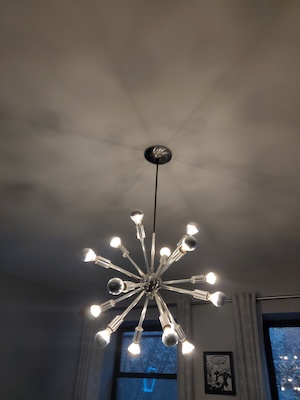
Figure 1. The Sputnik chandelier
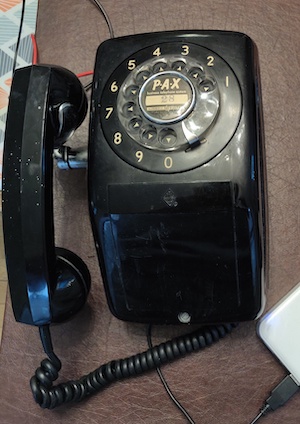
Figure 2. The rotary phone
Dimming the Chandelier
Reading the rotary phone from a microcontroller seemed pretty straightforward. Nathan Seidle published a tutorial on the Sparkfun blog fifteen years ago that would do the trick. Building an A/C dimmer in the wall was the harder part. I have yet to be satisfied with any of the DIY A/C dimmer circuits I’ve tested, and in-wall construction is beyond my comfort zone. But we have a Philips Hue hub, and a lot of Hue lamps, and I have examples of how to control the Hue system from a WiFi-enabled Arduino, so that seemed like a good approach.
Next problem: the Hue system communicates from the hub to the bulbs directly, and the bulbs for the sputnik are specialty bulbs, a G16 half-silvered bulb. So I started researching third-party Hue-compatible dimmers. Most of those are not actual in-wall dimmers, but I did find one that seemed to work, the Quotra Wireless Smart Dimmer Zigbee Light Switch.
I got of these dimmers, put it in the wall in place of the existing dimmer, and fired it up. It worked well for about an hour. Trouble was, I hadn’t properly calculated the load of the chandelier. Even though the lamps were only 15 watts each, with 12 of them it pushed up against the dimmer’s 180-watt limit. The dimmer overheated and stopped dimming, would only go on and off, and stopped responding to the Hue.
After looking for other dimmers, I decided the next best thing to do was to see if I could reduce the Sputnik’s load by switching to LED lamps. Seemed like a good idea for the power savings anyway. It took a few months, but I found dimmable G14 Candelabra LED Bulb, Half-Silvered, and as the lamps in the Sputnik died (the incandescent ones tend to run hot), I swapped them out for LED. Now the chandelier’s only 50 watts, well in the range for a Quotra dimmer. So I got another one and tried again, successfully.
Reading the Rotary Phone
With the dimmer in place, it was time to visit Nate’s tutorial. Sure enough, it was pretty easy to convert to modern Arduino code. The harder part was deciphering the wires of my phone. Mine is not a standard AT&T phone, so the wiring isn’t the same. But again, Nate’s tutorial was helpful there too. The dial worked just like his. Figure 3 shows the switches at the back of the dial. A little time with a multimeter, and I had the wiring worked out.
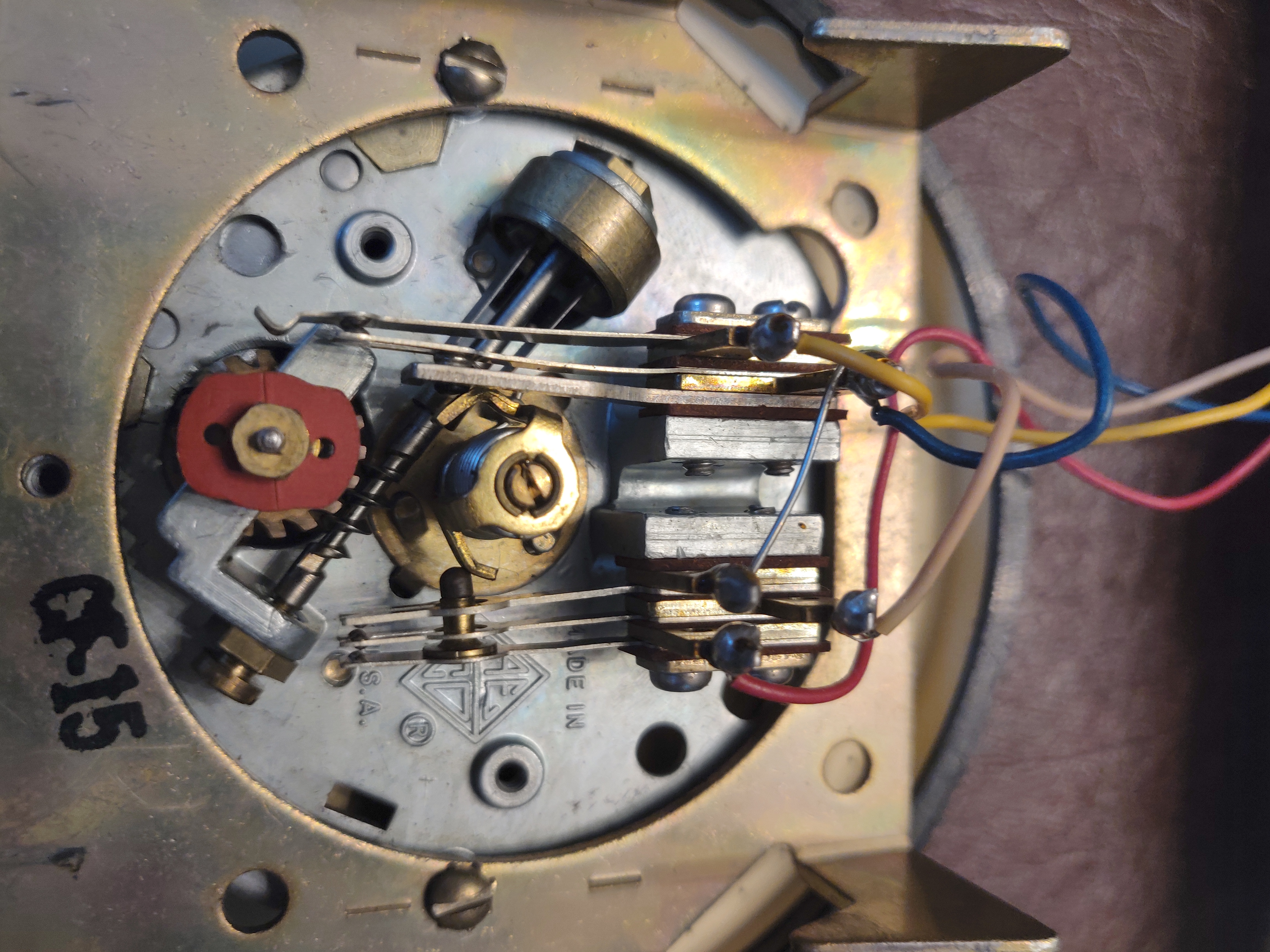
Figure 3. Rotary telephone dial from behind. There are basically two switches, one that switches at the beginning and end of dialing, and another that switches once for each number.
Figures 4 and 5 show the two terminal blocks inside the phone where all the wires go to. One is on the side of the phone and the other is in the front, under the dial. The relevant terminals were as follows:
- Front terminal block, terminal 5: cradle hook terminal
- Front block terminal 6: end rotary terminal
- Side terminal block, terminal 5: ground terminal
- Side block terminal 8: rotary terminal
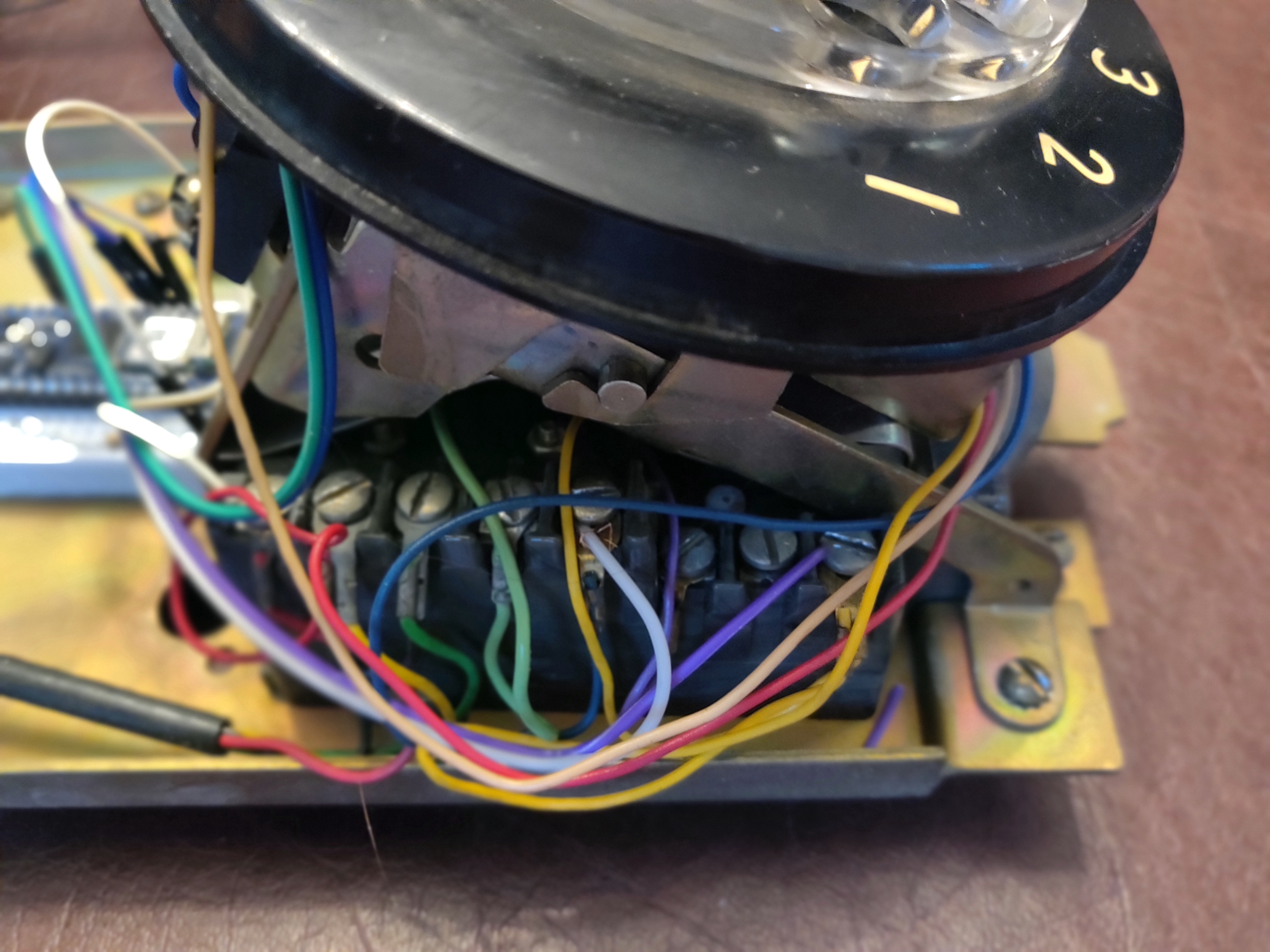
Figure 4. Side terminal block in the rotary phone.
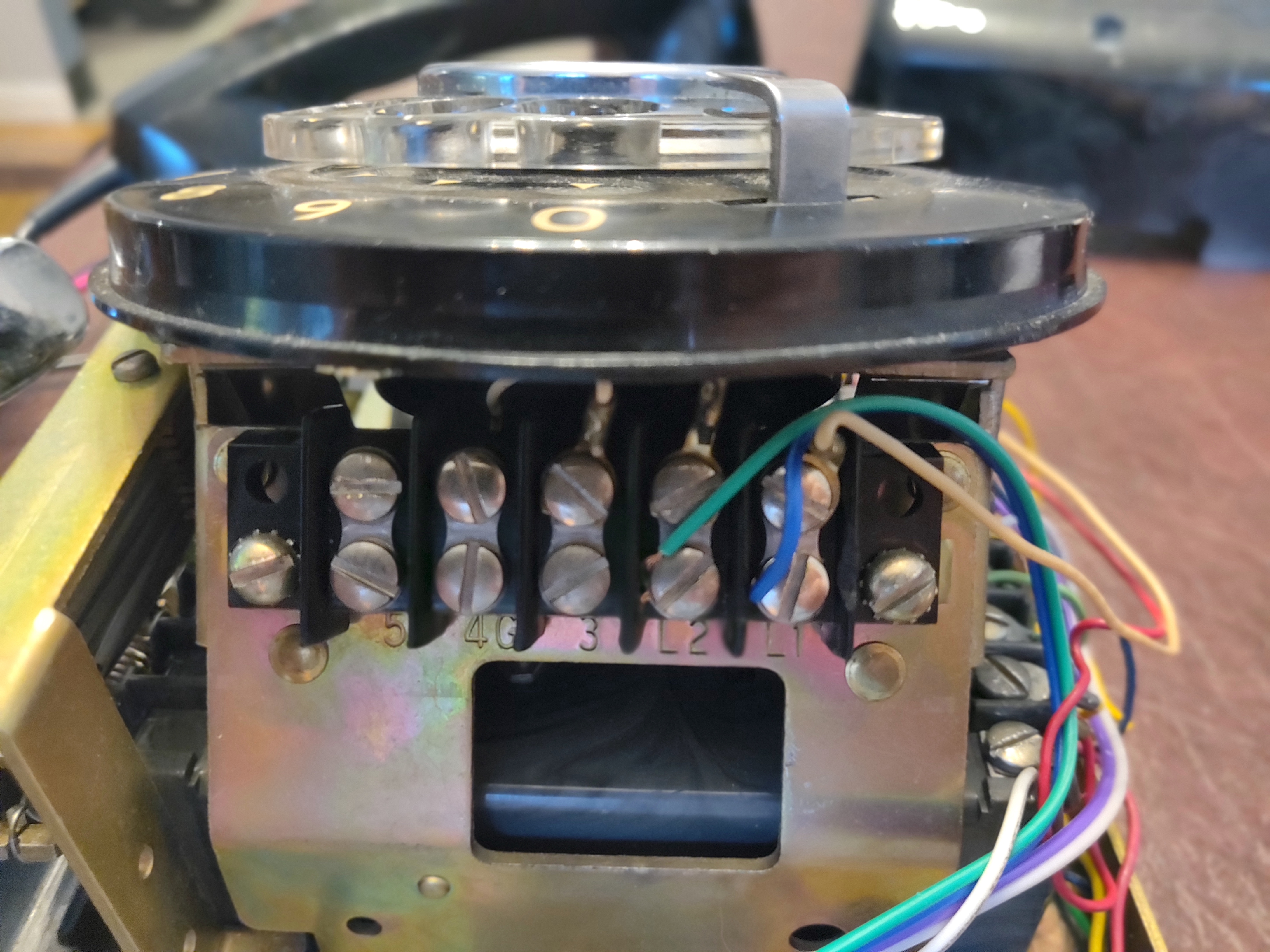
Figure 5. Front terminal block in the rotary phone.
Circuit
The circuit for this project is quite simple. The rotary phone’s dial, end rotary dial, and on/off hook terminals go to three of the Arduino’s interrupt pins (pins 0, 1, and 4, since I am using a MKR1000). The phone’s speaker terminal goes to pin 5 for generating tones, and the phone’s ground terminal goes to the MKR1000’s ground.
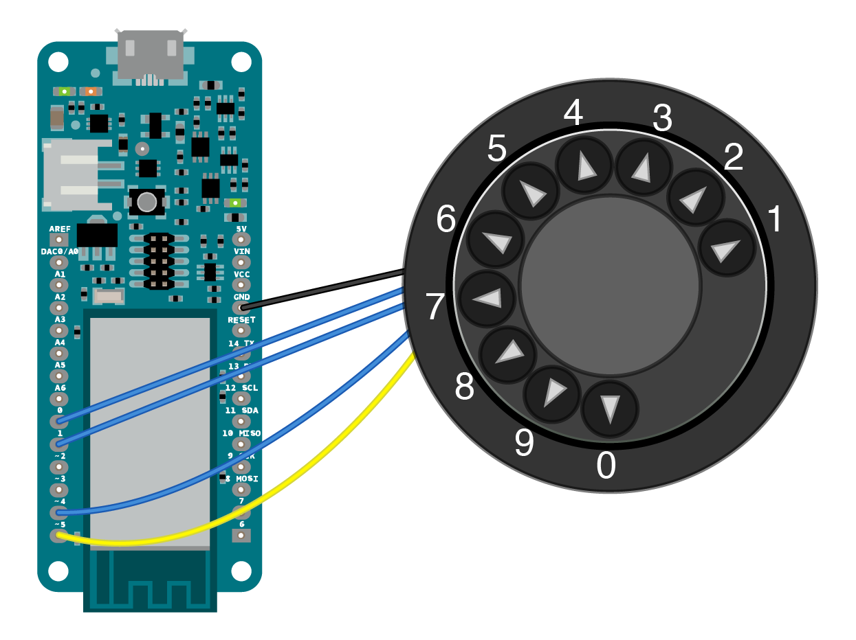
Figure 6. Breadboard view of the MKR1000 wired to the rotary phone dialer.
To connect the wires, I soldered screw terminals to the appropriate pins. This made it easier to test, remove, and re-mount the board.
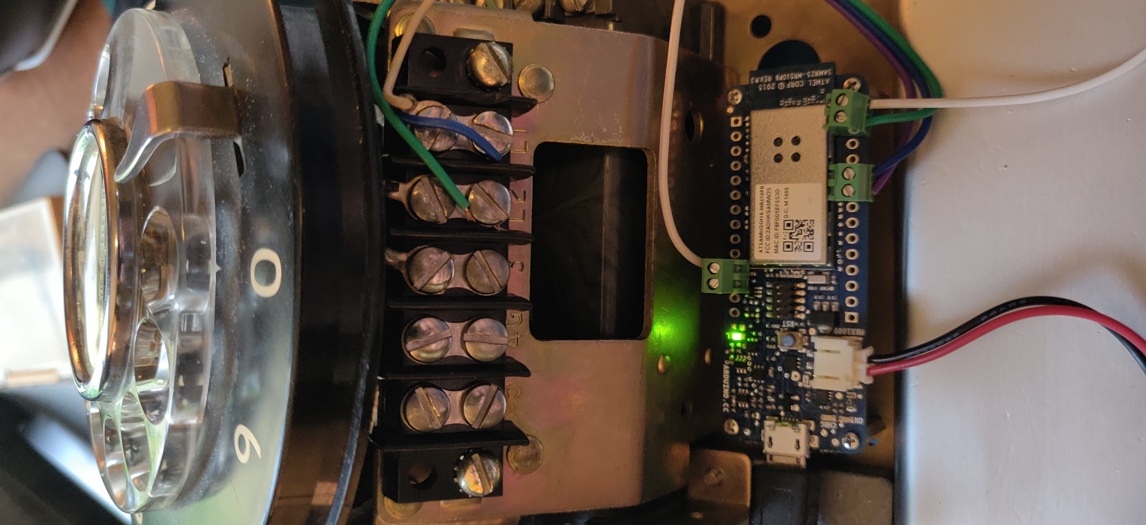
Figure 7. The MKR1000 mounted inside the phone on standoffs. It’s powered by the 8000ma Li-Poly battery beneath it.
Figure 7 shows the board mounted in the phone using standoffs, and powered using an 8000mA Li-Poly battery. I mounted a USB charging cable to the MKR1000 permanently so that I can charge the phone when needed. I used the WiFi101 library’s maxLowPowerMode() to ensure the radio goes to sleep when not in use, and the ArduinoLowPower library to put the main processor to sleep, waking it whenever the phone is picked up. With those two features, I tested and got about three to four days of battery life with hourly use of the phone.
User Interaction
With the wiring worked out, I started outlining a sketch for the WiFi boards. Since I had Hue examples already, I knew I’d use the ArduinoHttpClient to do the HTTP requests, and also the Arduino_JSON library to make the necessary JSON objects for the body of the requests. The first thing was to outline the behavior:
- Participant has to pick up the phone to dial
- Dialing any digit fades the light
- Hanging up the phone puts the processor to sleep
I decided to put the processor to sleep when not in action because I didn’t want to run in-wall power. With a decent phone charger, I could run the processor in sleep mode for a long time. But when the participant picks up, the processor will need time to re-connect to the network. How should I indicate that? The obvious answer was: dialtone means you have a network. No dialtone means you don’t.
After looking into generating DTMF tones from an Arduino, I decided I didn’t want to add the extra circuitry to generate the tones. All the examples I looked at were too hardware-specific to the Uno, and required 8 pins to work, so I faked it by generating the tones with the tone() command. It doesn’t sound quite right, but it’s good enough.
We mounted the phone next to the dining table for easy access to the chandelier and the table, as shown in Figure 8. You can see it in action in this video.
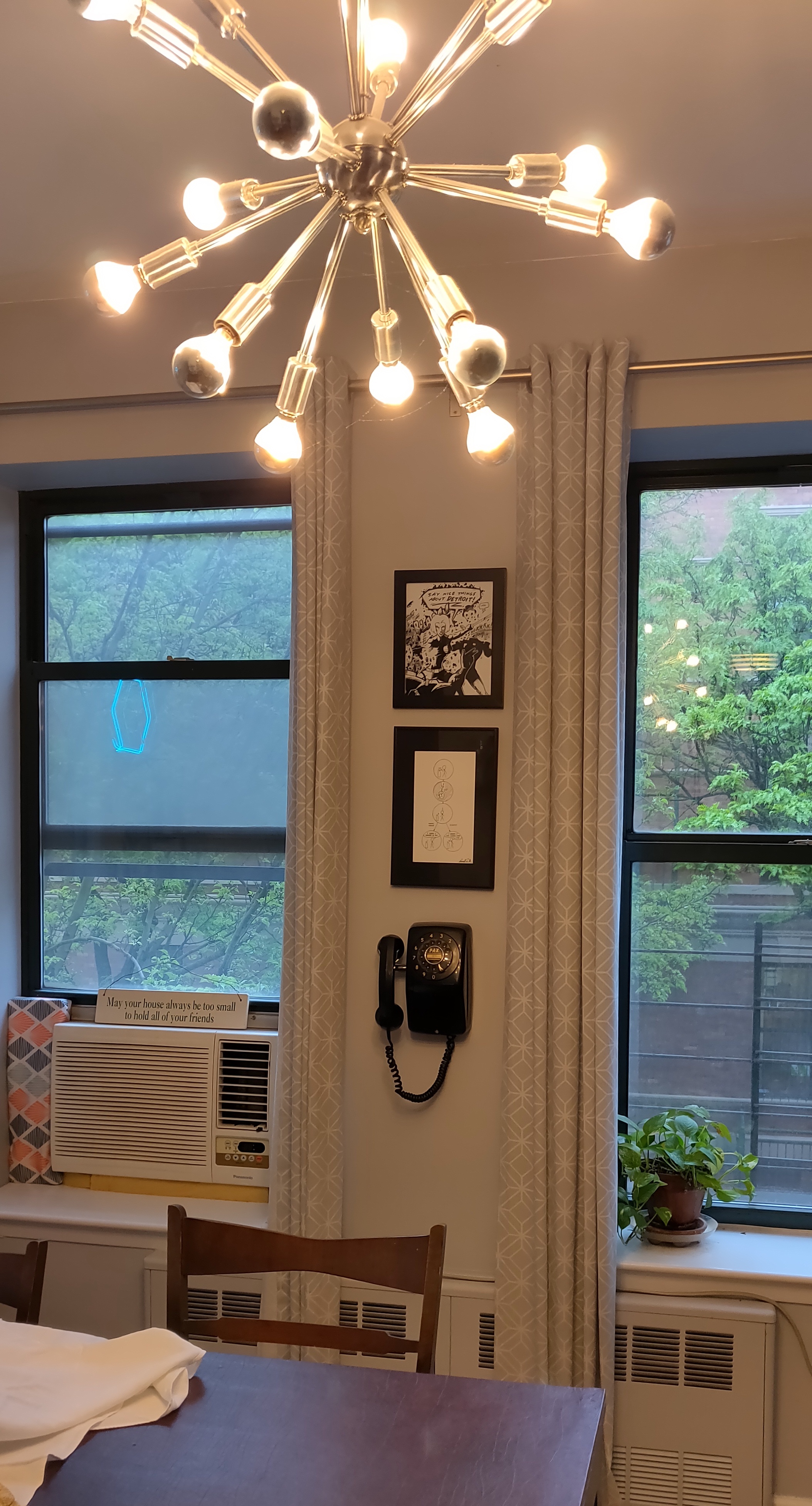
Figure 8. Rotary phone mounted near the dining table.
The Code
Here’s a pseudocode outline of the Arduino sketch for this.
// setup function:
  // Initialize serial
  // configure the inputs for the rotary phone
  // Initialize builtin LED for network status
  // attach interrupts for phone inputs
  // Attach interrrupt to hook to wake up processor

// loop function:
   // LED shows whether the WiFi is connected or not

  // if phone is hung up,
    // turn off dialtone
    // set a timer until sleep (now + 1 minute)

  // if phone is not hung up and not on the network,
    // try to connect


  // if the sleep timer has passed,
    // disconnect the WiFi
    // turn off the status LED
    // sleep

  // if dial is at rest and there is a recent dial count,
      // 1 is off, 10 is brightest.
      // map to a 0-255 range

      // Make a JSON object for the HTTP request
      // if there's a network connection and you're not hung up,
        // make the HTTP request
That’s the main logic of the program. The full sketch can be found at this link.