Light Projects
A collection LED control examples for Arduino
Low-voltage DC Lamps
LED Drivers
LED Strip Control
Addressable LEDs
NeoPixel Library Quickstart
Making Electronic Candles
Fading
Chromaticity
Color Spaces
Spectrometers
Light Rendering Indices
Inventory
Pattern Making
Telephone Dimmer for Philips Hue
Tom's other light-related repos
tigoe.github.io
This project is maintained by tigoe
Controlling Low-Voltage DC Lamps
The spread of LED lighting has made it much easier to create domestic lighting projects. Until recently, if you wanted to control the lights in your home or office, you needed a control circuit for high-voltage AC power. Although it is possible to control AC dimmer circuits from a microcontroller, it’s both more complex and less safe than working with low-voltage DC circuits. In contrast, low-voltage LED lamps are relatively easy to control from a microcontroller.
To control low-voltage DC lamps from a microcontroller, you’ll need a separate power source, and a transistor that’s matched to your voltage and current needs.
Be alert when shopping, as there are many LED lamps that operate on high-voltage AC on the market as well. These are not controllable using the method described here.
Electrical and Physical Characteristics
When you start to plan a DC lighting project, remeber the relationships between voltage, current, resistance, and electrical power:
voltage = current * resistance
and
electrical power (wattage) = voltage * current
Voltage - The most common voltages for DC lamps are +12V, and +24V. These are higher than the operating voltage of microcontrollers, but well within range of many transistors.
Current - The current that a lamp needs should be listed in its technical specs, but often you’ll only be given the wattage. If so, remember that wattage = voltage * current, and you can work out the current. For example, this 12-24V landscape bulb operates at 12V and consumes 5 watts. That means its current is about 0.4 amps.
You should leave some overhead in choosing a power supply; 20% is a good number. For example, if your lamp need 0.4 amps, then pick at least a 0.5 amp supply.
Equivalent Wattage - don’t be fooled by this number. It’s a measure of the equivalent incandescent lamp you’d need, but the number has no bearing on your circuit.
Lamp Shape and Base - different lamps come in different shapes and sizes, and have different bases. Always match your base to your lamp. There’s a great guide to standard base shapes and their names in Light Sources, Second Edition: Basics of Lighting Technologies and Applications, page 47, by Spiros Kitsinelis. You can find a partial summary on my lighting terminology page.
Bases you’ll commonly find in DC lamps are the smaller screw bases, the bi-pin base, the twist-lock base, and the wedge base. Bulbs.com has an excellent chart of bases. They also have a good lamp size and shape chart. Generally the larger lamp sizes are limited to high voltage lamps, but you’ll see candleabra lamps, MR-16 lamps like the JC bi-pin and the wedge frequently in 12V and 24V LED lamps.
Size note: The number in most lamp sizes refers to eighths of an inch. For example, a PAR64 lamp is a Parabolic Aluminized Reflector (PAR), 64/8” (8 inches) in diameter. An MR-16 is a Metallic Reflector (MR), 16/8” (2 inches) in diameter.
Light Characteristics
Color Temperature - Color temperature, measured in degrees Kelvin (°K), refers to the warmth or coolness of a light source. the higher the Kelvin temperature, the cooler the color hue. Here are the typical terms and their ranges in degrees Kelvin:
- warm white: ~3000K
- cool white: ~5400K
- natural white: ~4000K
- amber: ~1800-2000K
- daylight: ~6500K and above
Lumen output - the brightness of any light source can be measured in lumens. For a good description of the main physical terms used to quantify lighting, see this video from Philips. For more on this, see Kitsinelis, Spiros, Light Sources, Second Edition: Basics of Lighting Technologies and Applications or Descottes, Hervé; Ramos, Cecilia E., Architectural Lighting: Designing With Light And Space (Architecture Briefs) or my lighting terminology page.
Here’s an example of how to work with this information:
Illuminance, the density of light energy on a surface, decreases with the square of the distance from the source. Illuminance levels are usually given in lux, which is lumens/meters squared. So if you have a source that’s 450 lumens/m, and you expect it to light a wall that’s 2 meters away from the source, then the illuminance at the wall would be 450/4, or 112.5 lux. Here are some suggested illuminance levels:
- Incidental use: 200 lx
- General work/office use: 300 lx
- Task lighting: 5-700 lx
- Specialized work: 1000-1500 lx
- Midday sun: 32K – 100K lx
Illuminance levels are abstract until you measure them in a real space however. Although professional lux meters are expensive, there are many lux meter apps available for mobile devices that use your device’s camera. It’s worthwhile to download one and use it to get to know what different lux readings look like to your eye. App-based readings aren’t too accurate, but they give you the general idea.
Control Circuits
You can control 12-24V DC sources with power transistors or MOSFETs from a microcontroller. You can also control them from an LED driver. The three transistor models and the LED driver below work well for this purpose.
The control method here isn’t affected by whether your power supply is capable of dimming or not, because you’ll be doing the dimming yourself from a microcontroller. That said, some LED sources dim better than others, so you may have to shop around to find the ones you like.
In the circuits below, a transistor or LED driver is connected to a GPIO pin of the microcontroller. You can turn the light source on by taking the GPIO pin high, and turn it off by taking the pin low. You can dim the source by using pulse width modulation (PWM) to the pin. The LED fading examples in this repository can all work with these circuits.
The LED driver circuit is the most effective of these circuits for controlling an LED light source long term, as it will help regulate the current to keep the LED at a constant brightness while preserving lamp life. However, the transistor and MOSFET circuits will work for most simple applications.
TIP120 Darlington Transistor
The TIP120 transistor (datasheet) is a bipolar transistor, designed for high current inductive loads like motors. These transistors have been a staple in my projects for decades. Darlington transistors are actually two transistors in one, where the pairing of the two results in higher gain. The TIP120 has a built-in snubber diode to prevent damage from back-voltage generated by motors. You don’t actually need these things for controlling LEDs, but what makes the TIP120 useful is that it can control a load up to 60V and 5A and it can be controlled reliably by either a 5V or 3.3V output from a microcontroller.
The TIP120 transistor commonly comes in a TO-220 package that fits nicely into a solderless breadboard. If you’re holding the TIP120 with the tab at the top and the bulk of the component facing you, then the pins, from left to right, are: base, collector, emitter. The base is the control pin. The collector is where the electrical energy comes in, and the emitter is where it flows out to ground. The base should be connected to a 1 kilohm resistor, and the other side of the resistor should be connected to the GPIO pin of your microcontroller. The collector should be connected to the cathode of the LED source, and the emitter pin should be connected to ground.
Figure 1 shows the circuit for a TIP120 Darlington transistor controlling a 12V DC LED source from a MKR Zero. The same circuit can be used for a 24V source, with a different power supply. Figure 2 shows the same circuit with a Nano 33 IoT.
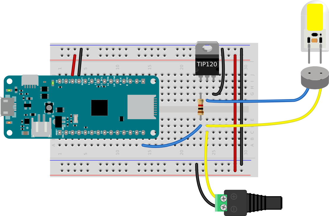
Figure 1. TIP120 transistor controlling an LED lamp from a MKR Zero.
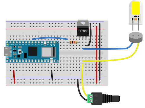
Figure 2. TIP120 transistor controlling an LED lamp from a Nano 33 IoT.
Circuit Description (Figure 1 and 2)
In Figure 1 and Figure 2, the microcontroller is straddling the center of a breadboard with its top pins plugged into row 1 of the board. Figure 1 shows a MKR Zero and Figure 2 shows a Nano 33 IoT. The Vcc pin (physical pin 26 on the MKR Zero, pin 2 on the Nano 33 IoT) is connected to the breadboard’s voltage bus, and the ground pin (physical pin 25 on the MKR Zero, pin 14 on the Nano 33 IoT) is connected to the ground bus. The voltage and ground buses on either side of the board are connected to each other. A TIP120 transistor is mounted in the right center section of the board below the microcontroller. The microcontroller’s pin D5 (physical pin 14 on the MKR Zero, pin 23 on the Nano 33 IoT) is connected to the base of the transistor through a 1-kilohm resistor in series with the base. The transistor’s emitter pin is connected to ground. The transistor’s collector pin is connected to the LED lamp. The other connector of the lamp is connected to the positive terminal of a +12V DC power jack. The power jack’s negative terminal is connected to the breadboard’s ground bus. The jack should be connected to a +12V DC power supply.
FQP30N06L N-Channel MOSFET
A MOSFET (Metal Oxide Semiconductor Field-Effect Transistor) is a slightly more modern transistor, designed specifically for switching applications. Bipolar transistors require a certain amount of current at the base to switch, while MOSFETs draw almost no control current. They’re ideal for switching LED sources. They are more sensitive to electrostatic discharge than bipolar transistors, though, so you have to be more careful not to accidentally expose them to a static shock. Make sure you’ve grounded yourself well before working with MOSFETs.
The FQP30N06L MOSFET commonly comes in a TO-220 package that fits nicely into a solderless breadboard. If you’re holding the FQP30N06L MOSFET with the tab at the top and the bulk of the component facing you, then the pins, from left to right, are: gate, drain, source. The gate should be connected to the GPIO pin of the microcontroller that you plan to use to control the LEDs. The drain should be connected to the cathode of the LED source, and the source pin should be connected to ground.
The FQP30N06L MOSFET (datasheet) is an N-channel MOSFET designed for switching high-speed circuits, and it’s perfect for switching LEDs. It can control up to a 60V, 30A load and can be switched from 3.3V or 5V.
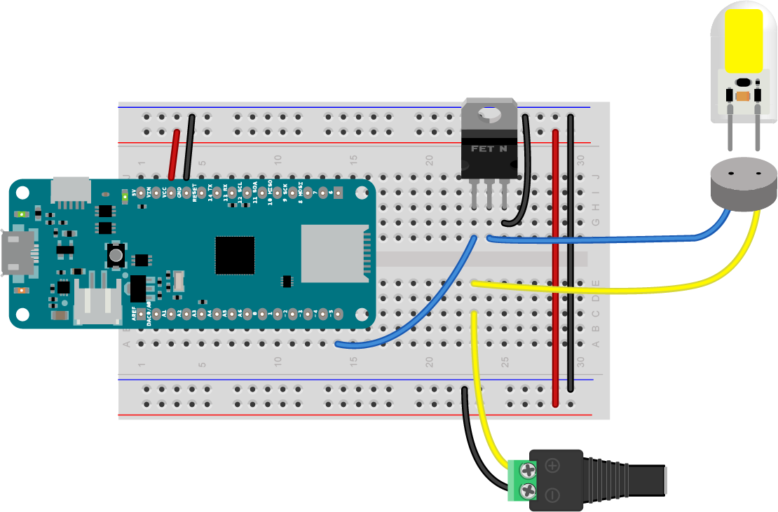
Figure 3. MKR Zero connected to a FQP30N06L MOSFET for controlling an LED lamp.
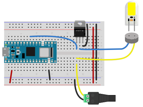
Figure 4. Arduino Nano 33 IoT connected to a FQP30N06L MOSFET for controlling an LED lamp.
Figure 3 shows the circuit for a MOSFET transistor controlling a 12V DC LED lamp from an Arduino MKR Zero. The same circuit can be used for a 24V source, with a different power supply. The wiring is similar to the TIP120 wiring, but the 1 kilohm resistors are omitted. Figure 4 shows the same wiring on a Nano 33 IoT board.
Circuit Description (Figure 3 and 4)
In Figure 3 and Figure 4, the microcontroller is straddling the center of a breadboard with its top pins plugged into row 1 of the board. Figure 1 shows a MKR Zero and Figure 2 shows a Nano 33 IoT. The Vcc pin (physical pin 26 on the MKR Zero, pin 2 on the Nano 33 IoT) is connected to the breadboard’s voltage bus, and the ground pin (physical pin 25 on the MKR Zero, pin 14 on the Nano 33 IoT) is connected to the ground bus. The voltage and ground buses on either side of the board are connected to each other. A MOSFET transistor is mounted in the right center section of the board below the microcontroller. The microcontroller’s pin D5 (physical pin 14 on the MKR Zero, pin 23 on the Nano 33 IoT) is connected to the gate of the MOSFET. The MOSFET’s source pin is connected to ground. The MOSFET’s drain pin is connected to cathode of the LED source. The anode of the source is connected to the positive terminal of a +12V DC power jack. The power jack’s negative terminal is connected to the breadboard’s ground bus. The jack should be connected to a +12V DC power supply.
IRLB8721 N-Channel MOSFET
The IRLB8721 MOSFET (datasheet) is similar in specs to the FQP30N06L. It too can control up to a 60V, 30A load and can be switched from 3.3V or 5V. The pin configuration for this MOSFET is identical to the FQP30N06L, so Figures 3 and 4 above will work with this part in place of the previous MOSFET with no other change.
NLDD1400H LED Driver
The circuit in Figure 5 shows how to control an LED lamp using a Meanwell NLDD1400H LED driver. The circuit in Figure 5 is powered by a +12V DC source plugged into the power jack on the left side of the circuit image in Figure 5.
The circuit is similar to the transistor circuits, in that there is one control pin coming from the Arduino, pin D5. Like the transistor examples above, this example can be controlled using the LED fading examples in this repository.
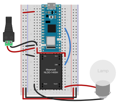
Figure 5. LED lamp controlled by a Meanwell NLDD1400H LED driver, which is driven by an Arduino Nano 33 IoT.
The input voltage range, i.e. the voltage difference between the Vin+ and Vin- pins is 10 - 56VDC (see the data sheet for more details.)
Circuit Description (Figure 5)
In Figure 5, the microcontroller is straddling the center of a breadboard with its top pins plugged into row 1 of the board. The Vcc pin (physical pin 2 on the Nano 33 IoT) is connected to the breadboard’s voltage bus, and the ground pin (physical pin 14 on the Nano 33 IoT) is connected to the ground bus. The voltage and ground buses on either side of the board are connected to each other.
The microcontroller’s ground pin (physical pin 14) is connected to the negative terminal of a 12V power supply jack. The microcontroller’s Vin pin (physical pin 15) is connected to the power supply jack’s positive connector. This powers both the microcontroller and the LED driver. The microcontroller’s pin D5 (physical pin 23 on the Nano 33 IoT) is connected to the DIM pin of the LED driver (pin 7 of the driver).
A Meanwell NLDD1400H LED Driver is mounted below the microcontroller, also straddling the center. The driver has 9 pins: 4 on the left and 5 on the right. They are, counting in the usual U pattern from upper left:
- Vin-(connected internally to pin 2)
- Vin-
- Vout- (connected internally to pin 4)
- Vout-
- Vout+ (connected internally to pin 6)
- Vout+
- DIM
- Vin+ (connected internally to pin 9)
- Vin+
The microcontroller’s pin D5 (physical pin 23 on the Nano 33 IoT) is connected to the DIM pin of the driver. The driver’s Vin- pins (pins 1 and 2) are connected to ground. The Vin+ pins (pins 8 and 9) are connected to the microcontroller’s Vin pin (physical pin 15) and to the positive terminal of the power supply.
The driver’s Vout- pins (pins 3 and 4) and Vout+ pins (pins 5 and 6) are connected to the two pins of a 12V LED lamp. These pins are not connected to the microcontroller’s voltage or ground at all. This is important, because they must be independent of the microcontroller’s supply in order to dim the lamp.
PCB Mounting of LED Drivers
It can be useful to mount a driver like this on a PCB with screw terminals and connect it to your test circuit with wires. This allows for some flexibility when you’re mounting the driver in the base of a lamp, for example, and it can also make testing drivers easier and safer. To that end, figures 6 and 7 show a NLDD1400H LED Driver mounted to a printed circuit board, from the front and back. Figures 8 and 9 show an alternate PCB layout. The circuit connections are the same as in Figure 5, but the wires are soldered in place.
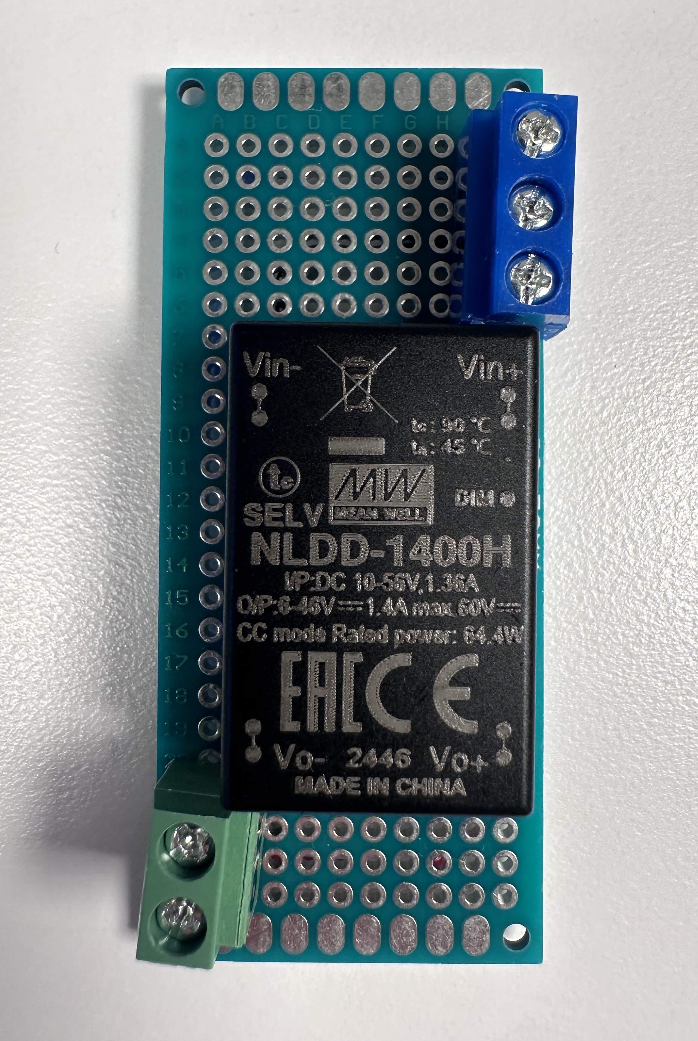
Figure 6. A Meanwell NLDD1400H LED driver soldered to a printed circuit board, with screw terminals for connections, front view.
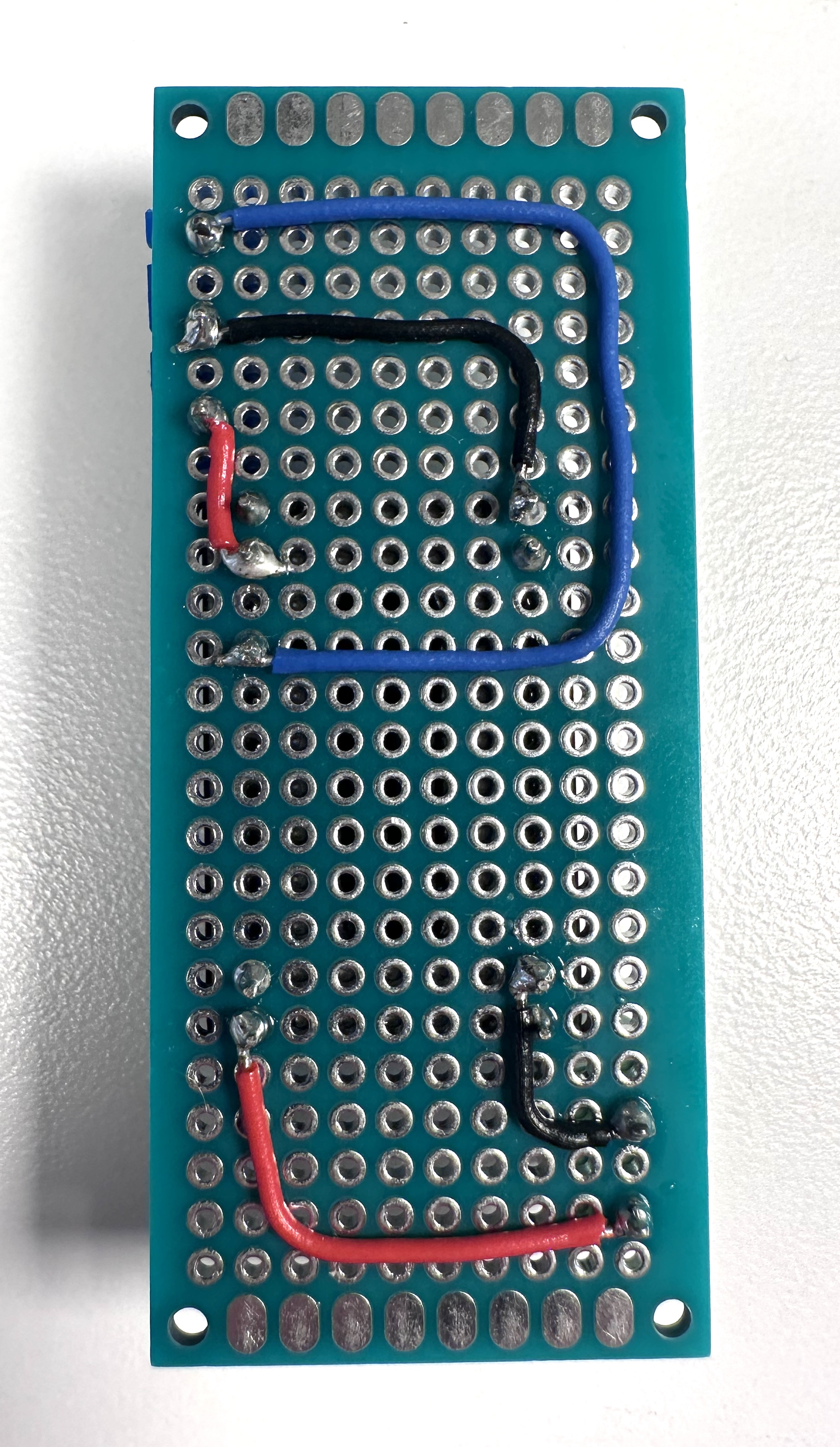
Figure 7. A Meanwell NLDD1400H LED driver soldered to a printed circuit board, with screw terminals for connections, back view.
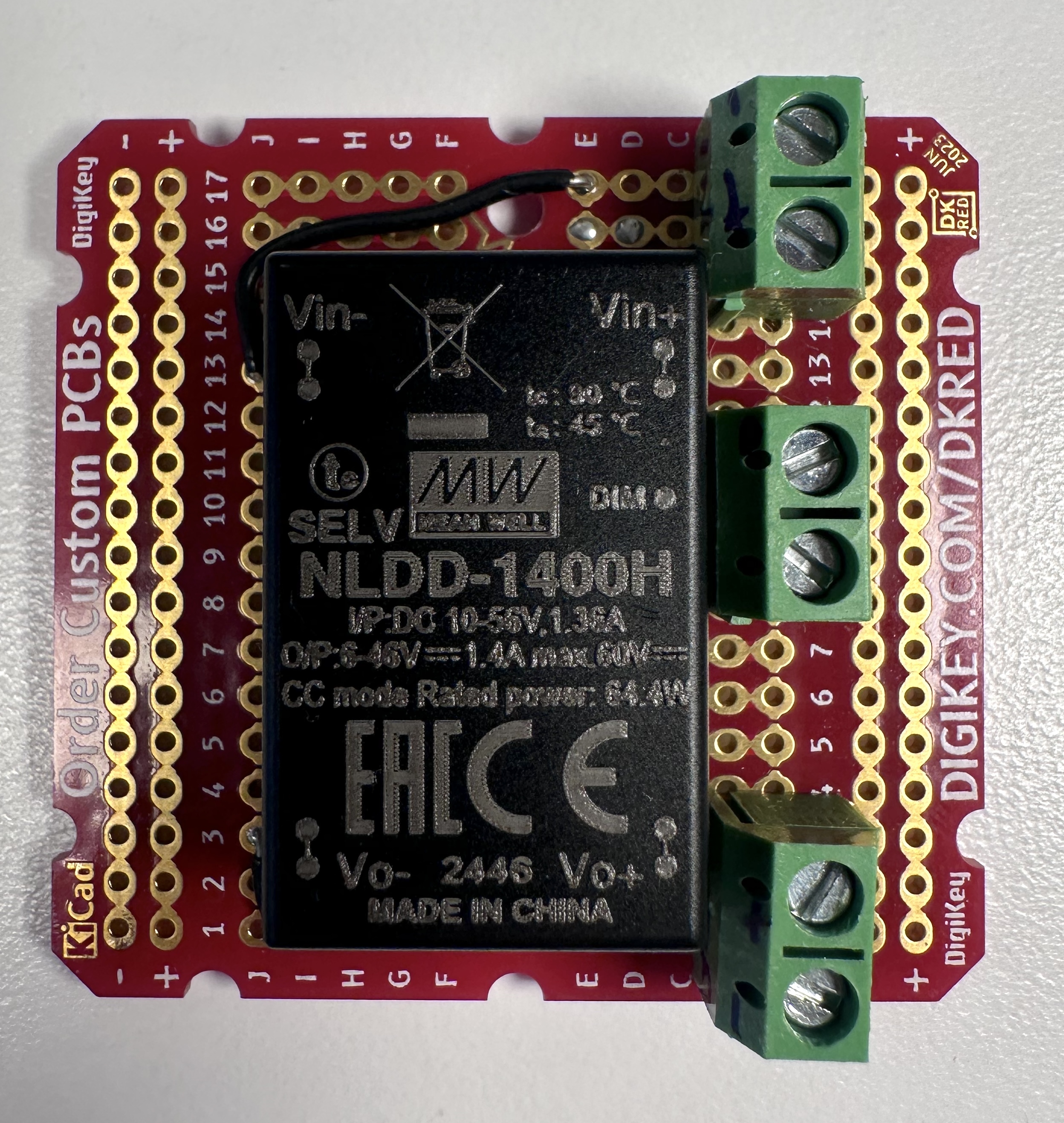
Figure 8. Alternate PCB layout. A Meanwell NLDD1400H LED driver soldered to a printed circuit board, with screw terminals for connections, front view.
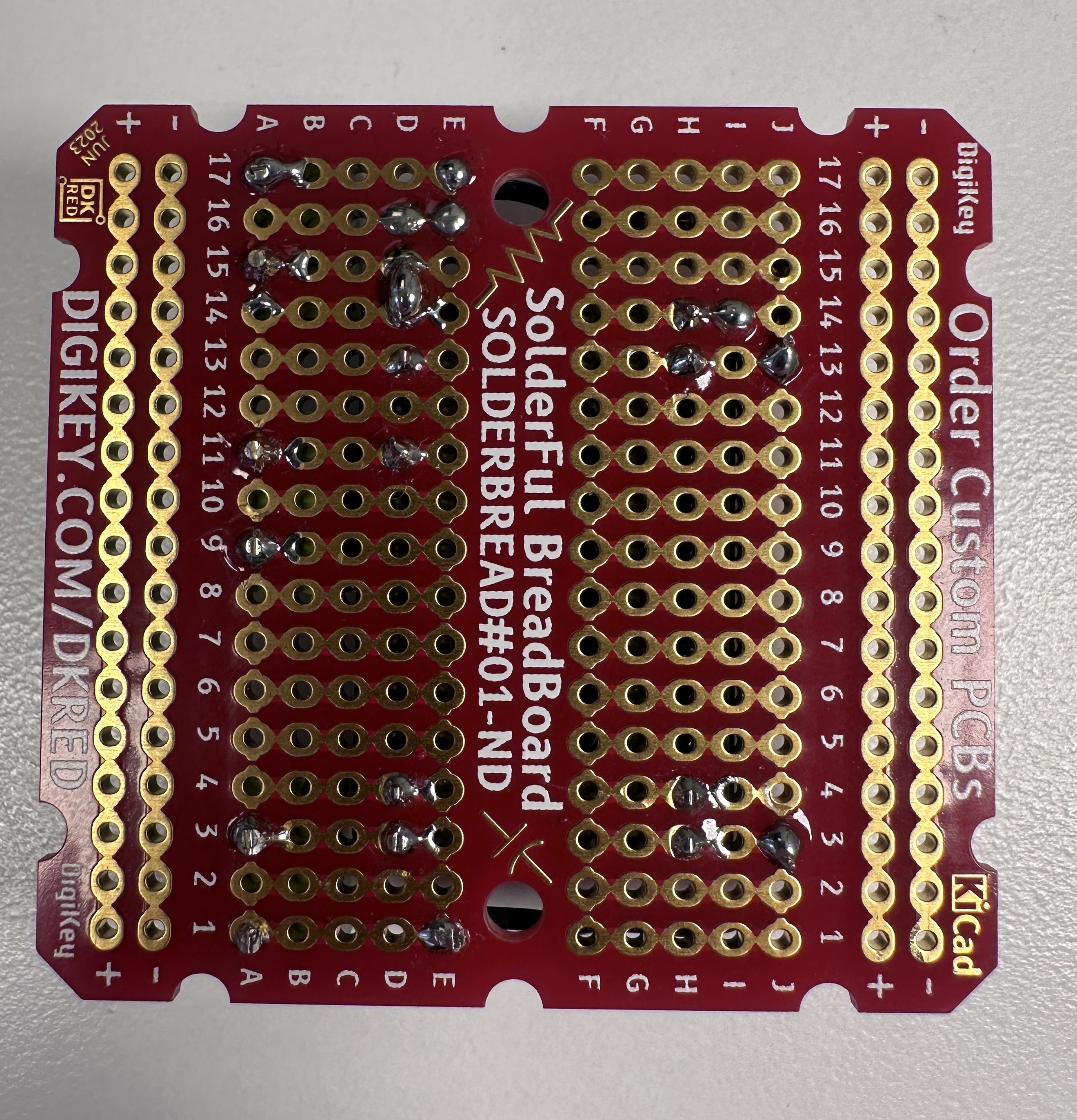
Figure 9. Alternate PCB layout. A Meanwell NLDD1400H LED driver soldered to a printed circuit board, with screw terminals for connections, back view.