Datalogging Examples
Examples of Datalogging Using Microcontrollers
tigoe.github.io
WiFi Datalogging
Node.js Datalogging Server
Google Sheets Datalogging Server
Tracking Time
MKR Series Datalogging
Home
This project is maintained by tigoe
Data Logging Examples for the MKR series Arduino Microcontrollers
The MKR series boards offer a number of ways to build networked dataloggers that can send data to remote devices via WiFi (MKR 1000, 1010, Vidor), Bluetooth LE (MKR 1010, Vidor), 3G cellular (MKR 1300), LoRaWan (MKR 1400), and LTE narrowband (MKR 1500). But the most immediate way is to write to an SD card. The MKR Zero has a built-in slot, the MKR Mem shield and others offer an external SD slot, and there are numerous SD card slot breakout boards from other retailers. The SD library supports all the Arduino boards, communicating with the SD card via SPI.
The realtime clock elements of these examples will also work with the Arduino Nano 33 IoT, which also uses the SAMD processor with the built-in RTC.
If you’re interested in using the network-enabled versions of these boards (MKR1010, MKR1000, MKR1400, MKR1500) to connect to a web app that logs the data, see the WiFi Datalogger tutorial.
Examples
- MKR_Interrupt_RTC_logger
- MKR_battery_SD_logger
- MKR_battery_LowPower_TimedWakeTest
- MKR_Datestamped_Files
Board Layout
For all the examples shown here will use the same default layout of the MKR series boards, as shown in Figure 1 below. The MKR Zero is mounted at the top center of the breadboard, straddling the center divide. The pins are numbered in a U-shape from top left to bottom left (physical pin numbers 1 to 14), then from bottom right to top right (physical pins 15 to 28). Each pin has a functional name in addition to its physical number. For example, physical pin 26 on the right (Vcc pin) is connected to the voltage bus on the right side of the breadboard. Physical pin 25 (GND) is connected to the ground bus on the right side of the board. The voltage and ground buses on the right are conected to the voltage and ground buses on the left, respectively.
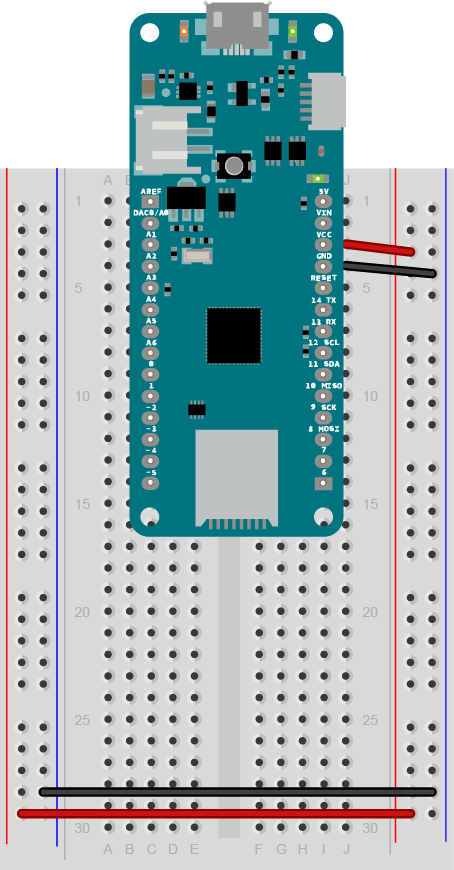
Figure 1. MKR Zero on a breadboard. This layout, described above, is standard for all the examples in this repository.
Formatting an SD Card
To use the SD library, you need to format your SD card as either FAT16 or FAT32. The MacOS Disk Utility application can sometimes make this troublesome, so here are instructions from the MacOS command line. Open the Terminal app and run the following command to list your disks:
$ diskutil list
You should get a response listing all disks, including a section that includes something like this:
/dev/disk2 (external, physical):
That’s your SD card. To format it, type the following command:
$ sudo diskutil eraseDisk FAT32 DISKNAME MBRFormat /dev/disk2
DISKNAME needs to be all caps, 8 characters or less.
Set the disk name based on the list of disks. For example, /dev/disk2 above comes from the list you got from diskutil list.
Writing to an SD Card
The minimal code to initialize an SD card and write to it is as follows:
 // initialize SD card:
  bool SDAvailable = SD.begin(SD_CHIP_SELECT);
  if (SDAvailable) {
    String logFile = "DATALOG.CSV";
    File dataFile = SD.open(logFile, FILE_WRITE);
    if (dataFile) {
        dataFile.println("Writing to the file");
        dataFile.close();
    }
  }
This routine is a useful check to see that your SD card is working. It’s also a good thing to put in setup to write a line of column headers to the file, if you’re planning a comma-separated values (CSV) file. The routine above takes about 12-18 milliseconds, depending on the length of the string to write.
File Names and Formats
File names on the SD card should be in the 8.3 format, i.e. eight characters long and a three-character extension. Consider using .CSV files if you’re writing multiple values for each reading, as they’re easy to open and parse in a spreadsheet later. Text files (.TXT) can work as well.
You can generate datestamped or timestamped filenames using the real-time clock if you want to. Here’s a function to open a file called DDMMYY.CSV, where the date is DD/MM/YY:
String fileNameFromDate() {
  String result = "";
  if (rtc.getDay() < 10) result += "0";
  result += String(rtc.getDay());
  if (rtc.getMonth() < 10) result += "0";
  result += String(rtc.getMonth());
  if (rtc.getYear() < 10) result += "0";
  result += String(rtc.getYear());
  result += ".CSV";
  return result;
}
Timing: millis() vs. Real-time Clock
You always need to keep time when datalogging. Though it’s simpler to use millis() to track elapsed time, there are a couple of drawbacks to it. First, it’s not as accurate as a real-time clock. Second, if you’re using any sleep functions, like the LowPower library, the millis() gets reset. For those reasons, it’s better to use a real-time clock. The MKR boards all have one on board, accessible using the RTC library. Using that library, you can set the time, get the hours, minutes, seconds, day, month, year, and Unix epoch. If you’re using one of the WiFi-enabled boards (MKR 1000 or 1010 or Vidor), you can also set the time from the network using the WiFi.getTime() command (here’s an example on the Arduino site). You can also set timed alarms which will wake the processor up if you put it to sleep to save power.
Setting the RTC From the Compiler
The C compiler has two reserved names, __TIME__ and __DATE__, that return the time and date that your program is compiled. They result in strings like this:
21:00:31
Apr 17 2019
You can use these to set the real-time clock in the startup function, by parsing the strings to get the values as numbers. Below are two functions, one to set the time from compile time, and another to set the date:
// set the rtc time from the compile time:
void setTimeFromCompile() {
  // get the compile time string:
  String compileTime = String(__TIME__);
  // break the compile time on the colons:
  int h = compileTime.substring(0, 2).toInt();
  int m = compileTime.substring(3, 5).toInt();
  int s = compileTime.substring(6, 8).toInt();

  // set the time from the derived numbers:
  rtc.setTime(h, m, s);
}

// set the rtc time from the compile date:
void setDateFromCompile() {
  String months[] = {
    "Jan", "Feb", "Mar", "Apr", "May", "Jun",
    "Jul", "Aug", "Sep", "Oct", "Nov", "Dec"
  };
  // get the compile date:
  String compileDate = String(__DATE__);
  // get the date substring
  String monthStr = compileDate.substring(0, 3);

  int m = 0;    // variable for the date as an integer
  // see which month matches the month string:
  for (int i = 0; i < 12; i++) {
    if (monthStr == months[i]) {
      // the first month is 1, but its array position is 0, so:
      m = i + 1;
      // no need to continue the rest of the for loop:
      break;
    }
  }

  // get the day and year as substrings, and convert to numbers:
  int d = compileDate.substring(4, 6).toInt();
  int y = compileDate.substring(9, 11).toInt();
  // set the date from the derived numbers:
  rtc.setDate(d, m, y);
}
Reading the Battery Voltage
If you’re running the MKR series boards from a LiPoly battery, it can be useful to check the voltage on the battery to make sure you’re properly charged. You can do this by reading ADC_BATTERY, an internal pin. The battery pin has a voltage divider across it that limits the max. voltage to 4.3 volts. You can read it and convert it to voltage or percentage like so:
    // read the battery:
    int adcReading = analogRead(ADC_BATTERY);
    // convert to a voltage:
    float batteryVoltage = adcReading * (maxBatteryVoltage / 1023.0);
    // and a percentage:
    float percentage = (batteryVoltage / maxBatteryVoltage) * 100;
Several of the examples read the battery voltage and log it in this manner.
Putting the Processor to Sleep
When you put the processor to sleep, it’s a helpful practice to use the built-in LED to indicate when it’s awake. You can put the processor to sleep using the RTC library’s standbyMode command like so:
rtc.standbyMode();
Or you can use the LowPower library. That library offers three modes of sleep: idle(), sleep() and deepSleep(). Each offers greater power savings than the previous, at the cost of slower restart. You can wake the processor up using a timed sleep, or using an external interrupt pin.
When the processor is asleep, it won’t show up as a serial port, which can make reprogramming tricky. Two simple tricks make programming workflow with sleep functions easier:
- Put a
delay()in the setup, 1-3 seconds, so that the processor stays awake a bit longer and acknowledges upload from the IDE. This is also useful if you’re printing any diagnostic info in the setup. - When the processor is asleep, double-tap the reset button to put it in bootloader mode. The bootloader will start and the processor will show up as a serial device, but the sketch won’t start, so it won’t go to sleep. This makes it easy to reprogram.