DMX Examples
A collection DMX-512 control examples
tigoe.github.io
DMX_Examples Home
DMX/sACN Intro
TouchDesigner DMX settings
Arduino:
Arduino DMX
Arduino sACN
JavaScript:
JavaScript node.js sACN example
JavaScript WebSerial DMX
This project is maintained by tigoe
ArduinoDMX
The ArduinoDMX library, originally written to work with the MKR series Arduinos and the MKR485 shield, will also enable you to send DMX-512 out from any Arduino to control DMX fixtures. This library uses the ArduinoRS485 library and an RS485 transceiver chip like Maxim’s MAX485 chip to send DMX data. It can work with other RS-485 transceiver chips in the same family from Maxim as well.
Bill of Materials
- Arduino (these examples have been tested successfully on the Nano 33 IoT; Nano Every; Uno; Leonardo; and Mega2560. They do not work on the Nano 33 BLE or the Due)
- Arduino MKR485 shield (if you’re using one of the MKR series Arduinos) or
- MAX485 RS485 transceiver IC
- 120-ohm resistor - for RS485 termination of cables and connectors
- XLR 5-pin female connector. You can do it with a 3-pin connector as well.
For reference, The Arduino circuits described here use these breadboard layouts and these microcontroller pin arrangments.
Circuit
If you’re using a MKR series Arduino and a MKR485 shield, you can simply plug the shield into the MKR board, connect an XLR connector to the shield, and you’re ready to go. For other models, you’ll need to connect your Arduino to a MSX485 chip, which will output the RS485 serial protocol on which DMX-512 depends.
Connect your Arduino to a MAX485 chip as shown in Figure 1. The ArduinoRS485 library uses the following pins:
- Serial TX - on any board that has more than one hardware serial port, you should use the second one, i.e.
Serial1. On the Uno and the Nano Every, there is only one hardware serial port, so you need to use that port, which is connected to pins 0 (Rx) and 1 (TX). The Arduino’s Serial TX will connect to the MAX485’s Driver Input (DI) pin. On the Uno, Serial TX is digital pin 1. On the Nano, it’s physical pin 16. - Serial RX - just as with serial TX, use the
Serial1port if there is one, otherwise use the only serial RX pin. Serial RX will connect to the MAX485’s Receiver Out (RO) pin. On the Uno, Serial RX is digital pin 0. On the Nano, it’s physical pin 17. - A5 - connect to the MAX485’s Read Output Enable (RE) pin. On the Nano, that’s physical pin 9.
- A6 - connect to the MAX485’s Driver Output Enable (DE) pin. On the Nano, that’s physical pin 10.
- Vcc and Ground - Connect the Vcc and ground pins of the MAX485 chip to the ground and Vcc pins of your microcontroller.
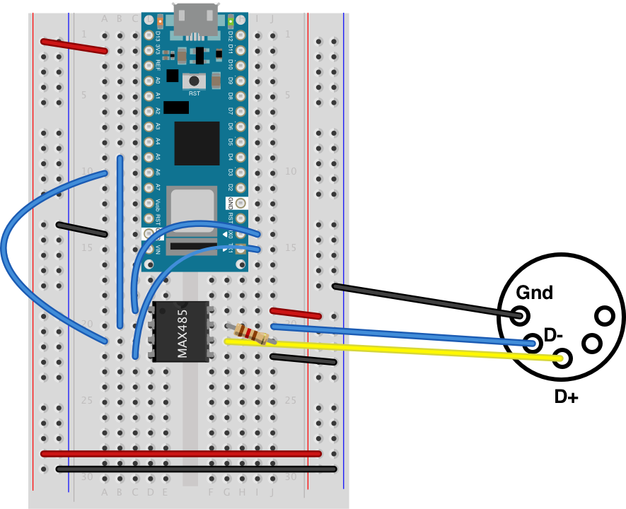
Figure 1. Arduino Nano 33 IoT connected to a MAX485 chip. The MAX485 is a DIP package. Its pins, reading in a U-pattern from top left, are RO, RE, DE, DI, GND, A, B, Vcc. The pins are connected as described above. This same diagram works for other Maxim RS-485 chips, including the MAX481, MAX483, MAX485, MAX487, or MAX1487, which share the same pin configuration. For more on the connector, see below in the text.
Note: on the Uno, you will not be able to use the Serial Monitor for debugging messages because the ArduinoRS485 library takes over the hardware serial port. Check this on the Every too
Connect a DMX Connector
Connect a 120-ohm resistor between the MAX485’s A and B output pins, and then connect the pins to the D+ and D- pins of a 3-pin or 5-pin female XLR connector, depending on the type of connector your DMX fixtures need. Connect them following the DMX-512 standard layout. The pins in an XLR connector are arranged in a half circle. When facing the rear of a female XLR connector with the half circle of pins on the bottom, the pin numbers are arranged as follows, from left to right, counterclockwise:
- 3-pin: ground, D+, D-
- 5-pin: ground, D-, D+, D2-, D2+
The wiring from the MAX485 to the XLR connector is as follows:
- MAX485 pin 6 to the DMX connector’s D- pin
- MAX485 pin 5 to the DMX connector’s D+ pin
- Connector’s ground pin to the ground of your circuit.

Figure 2. Pin diagram for 3-pin DMX connectors. Facing the male connector, and counting clockwise from left, the pins are: ground, DMX 1 Data-, DMX 2 Data+. Image from mediarealm.com.au

Figure 3. Pin diagram for 5-pin DMX connectors. Facing the male connector, and counting clockwise from left, the pins are: ground, DMX 1 Data-, DMS 2 Data+, DMX 2 Data-, DMX 2 Data+. Image from mediarealm.com.au
MKR485 Shield Connections to DMX Connector
If you’re using a MKR485 shield, connect the DMX connector as follows:
- MKR485 shield ISO GND connected to DMX connector GND
- MKR485 shield Y pin connected to DMX connector D+
- MKR485 shield Z connected to DMX connector D-
- MKR485 shield jumper positions: Z \/\/ Y set to ON
Examples
Once the circuit is ready, you can use any of the following examples or the library’s examples to get started.
- DMX Fade knob: fades a DMX channel based on the value of a potentiometer. Sends the DMX signal every 30ms.
- DMX Fade multi channel: fades each of the first four DMX channels from 0 to 255 and back to 0. When it finishes with each channel, it moves on to the next channel.
- BLE to DMX: creates a BLE peripheral with three characteristics, and sends the values of those three characteristics as DMX channel values when the characteristics change. Works on a BLE-capable board like the Nano 33 IoT or Nano 33 BLE only.