SensorExamples
A collection of examples on how to interface sensors to Arduino microcontrollers
MPX2012 Pressure Sensor
This example reads the value from an MPX2012 pressure sensor attached to a baby aspirator bulb. The result is a squeezable controller.
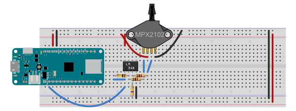
The pressure sensor has a typical output range of about 40mA, according to the MPX2102 datasheet. When powered at 3.3V from a MKR Zero board, the sensor’s outputs output a resting voltage around 1.6V. Based on this information, I used an op amp calculator on daycounter.com to calculate the resistance values for a differential op amp configuration. Figures 1 and 2 below shows the configuration I ended up with.
The LM358 op amp is powered from the Vcc pin of the microcontroller, a MKR Zero, so the voltage across the op amp is 3.3V. Pin 8 is the op amp’s Vcc pin, and pin 4 is the ground. The inverting and non-inverting inputs of the op amp (pins 2 and 3) are connected to the pressure sensor’s outputs through 1 kilohm resistors. A 100 kilohm resistor is the feedback resistor, connecting the op amp’s output (pin 1) to the inverting input (pin 2). A 470 kilohm resistor is connected from the non-inverting input (pin 3) to ground. THe sensor is also connected to ground and Vcc on its pins 1 and 3, respectively.
Images made in Fritzing and Illustrator CS.

Figure 1. Breadboard view ofMKR Zero and MPX2102 pressure sensor

Figure 2. Schematic view of MKR Zero and MPX2102 pressure sensor